Symbols
Notes & Syntax
4.1.1 Notes
This section explains how to define symbols in MapServer.
Note:
The definition of l Symbol can be in MapFile or in a separate file. ~ in ~ MAP Object to specify the corresponding Symbol file using the SYMBOLSET keyword, which can be reused symbol file.
l There are three types of Symbol in MapServer that can be used to render points, lines, and faces.
N Vector: VECTOR, ELLIPSE and its subtype Hatch
N Bitmap:
N TrueType:
l Symbol number 0. Point 0 represents a single pixel; for ~ shadowing 0, it represents a The solid fill; alignment line 0 represents a line that is one pixel wide.
l Symbol does not define color-related content, and color settings are defined in CLASS (except for bitmap Symbol of type)
l A maximum of ~64 symbols are defined in each symbol file. This parameter can be adjusted by modifying the value of MS_MAXSYMBOLS in the mapsymbol.h file.
4.1.2 Syntax
1) NAME:~ alias. The name used in ~ CLASS. ~ value: ~[string]
2) symbol types supported by TYPE:MapServer:
l Vector: a simple user-defined symbol (A simple drawing is used to define the Shape of the symbol).
The radius value of the direction of l Ellipse:XY.
l Pixmap: (Bitmap Symbols): symbols that support GIF and PNG images.
l TrueType: can be defined in FONTSET
Value:[vector | ellipse | hatch | cartoline | pixmap | truetype | simple].
4.1.2.1 Vector / Ellipse specific parameters
1) POINT: Define the starting point of the vector symbol or the radius of the ellipse in the XY direction. End the definition with END. The unit of coordinate is pixel, please define its default value before using it. You can insert some non-negative coordinates in place to create a non-adjacent path. For oval symbols you should provide the XY radius, if X and Y are equal then it is a circle.
Value:[x y][x y]. END
2) STYLE:Defines a dash style or pattern. Value:[num on][num Off][num on]...
END .
3) FILLED:~ sets the filling color. For symbols of type ~ MARKER, if OUTLINECOLOR Has been set, then the symbol has the same boundary line. Value:[true | false].
4.1.2.2 Pixmap specific parameters
1) IMAGE: PNG or GIF representing symbols The path to the file. Value:[path/filename]
2) TRANSPARENT: input GIF or PNG The fill color when the picture is set to be transparent, or define
Whether all shadow symbols should have transparent fill colors. By default, the background color matches the color of its parent picture. Value:[color Index]
4.1.2.3 TrueType specific parameters
1)Name of the font ~. Value: ~[char]
2) CHARACTER:~ can refer to a special ~ TrueType The character of the type font. ~ value: ~[char]
3) whether the ANTIALIAS:~ font is smooth. Value: ~[true | false]
4) GAP:~ is in pixels. Define ~ TrueType The distance between lines. Value:[integer]
4.2 Vector Symbols
There are four vector types of symbols: VECTOR, ELLIPSE, HATCH and CARTOLINE. You can define the representation of points, the representation of lines, and the representation of surfaces.
4.2.1 Defining Point Representations
You can use a coordinate sequence to define a vector symbol or you can define a specified XY The ellipse of the radius to define the vector symbol.
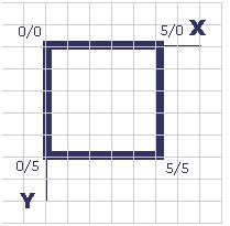
The mapfile corresponding to the above figure is as follows (note that the starting coordinates are the same as the ending coordinates):
SYMBOL
    NAME  "Square"
    TYPE      VECTOR
    FILLED  TRUE
    POINTS
    0 0
    0 5
    5 5
    5 0
    0 0
    END
END
In theory, the best way to construct the above symbols is to use a square style, which does not need to be so complex.
The above symbols can be written using the corresponding mapfile code, which can be found in chameleon. Reference the etc/symbols.sym file. Tip: the "- 99-99" coordinate looks like a fence, but it is only used on unfilled symbols.
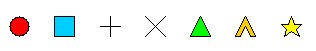
Examples of combined use of vector symbols:
LAYER
NAME "Test Symbols"
TYPE POINT
STATUS ON
CONNECTIONTYPE OGR
CONNECTION "test\_symbols/test\_sym.TAB"
HEADER "test"
CLASSITEM "test"
 CLASS
  NAME "Combined Symbol"
  EXPRESSION "Combined"
    STYLE
     COLOR 0 0 255
     OUTLINECOLOR 0 0 0
     SYMBOL 'Square'
     SIZE 40
    END
    STYLE
     COLOR 200 200 255
     SYMBOL 'Circle'
     SIZE 30
    END
    STYLE
     COLOR 0 0 255
     SYMBOL 'Cross'
     SIZE 20
    END
  END
END
The result of the above code is as follows:

4.2.2 Defining Line Representations
The basic vector symbol consists of a series of points.
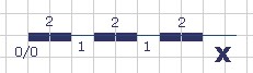
The contents of the mapfile file corresponding to the above figure are as follows:
SYMBOL
  NAME "dashed-line-short"
  TYPE ELLIPSE
  FILLED TRUE
  POINTS 1 1 END
  STYLE 2 1 END
END
Refer to the corresponding Symbol file to learn the configuration of the above figure.
vectors.sy ^ m ^ Example of < http://umn.mapserver.ch/MapServer/en/symbols/vectors.sym> combination line:
LAYER
NAME "Test Line Symbology"
TYPE LINE  STATUS ON
CONNECTIONTYPE OGR
CONNECTION "test\_symbols/test\_Lines.TAB"
HEADER "test"
CLASSITEM "test"
 CLASS
  NAME "Combined Line Symbology"
  EXPRESSION "Combined"
    STYLE
     COLOR 0 0 255
     SYMBOL 'continue'
     SIZE 7
    END
    STYLE
     COLOR 255 255 0
     SYMBOL 'continue'
     SIZE 5
    END
    STYLE
     COLOR 0 0 0
     SYMBOL 'dashed-line-short'
     SIZE 1
    END
  END
END
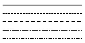
The display results are as follows:

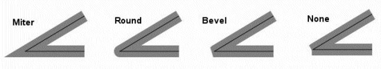
Cartoline Line type:
SYMBOL
  NAME "cartoline"
  TYPE cartoline
  LINECAP round \#\[butt|round|square|triangle\]
  LINEJOIN miter \#\[round|miter|bevel\]
  LINEJOINMAXSIZE 3
  STYLE
    40 17 1 17 1 17 1 17
  END
END
Where LINEJOINMAXSIZE defines the maximum length for miter type of joins As a factor of M to avoid spikes when d (3 means i.e. M = 3 times d) Lines are almost parallel:
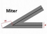
M = 3D
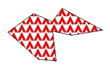
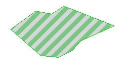
An example of defining faces with shadows:
The SYMBOL file is as follows:
SYMBOL
   NAME 'hatch-test'
   TYPE HATCH
END
The definition of LAYER in Mapfile is as follows (nds up with a 45 °hatching, with 3 pixels Thick lines, 10 pixels apart:)
LAYER   ...
  CLASS     ...
    STYLE
      SYMBOL 'hatch-test'
      COLOR 255 0 0
      ANGLE 45
      SIZE 10
      WIDTH 3
    END
  END
END
4.2.3 Defining Line and Area Representations using Symbols*
The following example is a combination of the above two, we can make a linear pentagram sequence.
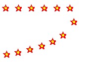
The process of making this symbol is as follows:
- Define symbol
SYMBOL
NAME "star-dots"
TYPE VECTOR
FILLED TRUE
POINTS

  0 0.375

  0.35 0.375

  0.5 0

  0.65 0.375

  1 0.375

  0.75 0.625

  0.875 1

  0.5 0.75

  0.125 1

  0.25 0.625

END

STYLE 1 25 END
END
- The chunk of the MapFile definition using as well the OVERLAY option:
CLASS
NAME "Hall of Fame"
EXPRESSION "star-dots"
COLOR 255 0 0
SYMBOL 'star-dots'
SIZE 14
OVERLAYCOLOR 255 255 0
OVERLAYSYMBOL 'star-dots'
OVERLAYSIZE 6
END
You can use techniques similar to the above to make the following symbols. "
Example of diagonal fill:
SYMBOL
NAME "diag45fill\ _ thin"
TYPE vector
TRANSPARENT 0
POINTS
0 1 1 0
END
END
4.3 Bitmap Symbols
Defining symbols of bitmap type requires pictures in either gif format or png format. Define a picture in this format
The methods are as follows:
SYMBOL
NAME 'Image'
TYPE PIXMAP
IMAGE 'bitmaps/image.gif'
END
The path to the above picture must be absolute or relative to the symbol file.
Optionally, you can use TRANSPARENT\ [color index] to set a transparent color. If you set up
The output image format IMAGETYPE does not support transparency, so you must set it in the corresponding layer.
TRANSPARENCY ALPLA.
4.3.1Create Bitmap symbol***
4.3.1.1 Introduction to Bitmapsymbols**
Advantages of Bitmap symbols:
Full color
fancy imaging effects such as buttonize, shadows, light and so on
Transparency
Easy to create
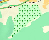
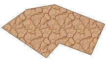
4.3.2 Filling areas with Bitmap symbols
Using Bitmap symbols can create a good filling effect. It should be noted that when you use Bitmap symbols to fill areas, you cannot change the size of the symbols, so In some cases you need to create different scale symbols for different scale maps. Example:
Symbols used
Filling effect of face area


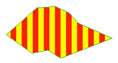

Some of the Mapfile are as follows:
LAYER
NAME "Test Symbols Poly"
TYPE POLYGON
STATUS ON
CONNECTIONTYPE OGR
CONNECTION "test_ symbols/test_ sym_ layer.TAB"
HEADER "test"
CLASSITEM "test"
CLASS
 NAME "Vertical Hatching Sample"

 EXPRESSION "hatch"

 COLOR 255 0 0

 OUTLINECOLOR 0 200 0

 SYMBOL 'Vertical\_Hatch'
END
END
4.3.3 Links below the symbol collection can download some free symbol files:
4.4 TrueType Symbols
TrueType is required to define TrueType type symbols Font file. In Mapserver, you can use FONTSET to specify the corresponding font file. The definition in the font file is as follows:
arial-bold    fonts/arialbd.ttf
arial         fonts/arial.ttf
arial-italic  fonts/ariali.ttf
The file contains two columns, the first column is used in the MapFile file, and the second column is used to specify the font file that contains the path.
You can define symbols of type TrueType in the mapfile file, or you can write the corresponding information to the
In a separate file, and then use SYMBOLSET in mapfile To reference this file. The latter is recommended so that reuse can be achieved.
Example of the definition of TrueType type symbols:
SYMBOL
   NAME "SurveyPoint"
   TYPE TRUETYPE    FONT "SURVEY"
   CHARACTER "."
END
The FONT name used here needs to correspond to the value in the file specified by FONTSET, CHARACTER
The following values can be used for:
l a,b,c,d„„ similar ASCII text
l Or use the following syntax for character numbers, such as "r", you can use the "Character Map" tool (Start-Programs-Accessories-System Tools-Character Map) to check the corresponding character map. In the lower left corner of the Character Map tool window you can see the UNICODE character and ASCII text description of the currently selected character. As shown below:
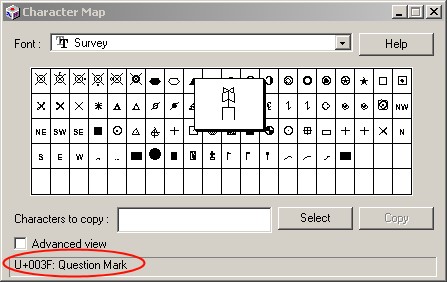
In the image above:
l ASCII character is: Question Mark = "?"
l Unicode number 003F (hexadecimal number) is the character\ # 63 in Symbol We can define it in the file as follows:
SYMBOL
    NAME "Windrose"
    TYPE TRUETYPE
    FONT "SURVEY"
    CHARACTER "?"
END
The following results are the same as the above:
SYMBOL
    NAME "Windrose"
    TYPE TRUETYPE
    FONT "SURVEY"
    CHARACTER "&\#63;"
END
4.4.1 Create symbols of type TrueTyp with many existing TrueType
Type of posture can be used, such as in the Corel Draw package with The font. You can use them to create your own fonts:
l Under the windows platform, you can use [Font Creator] Program.] (http://www.high-logic.com/products.html)http://www.high-logic.com/products.html
l Used under linux FontForge < http://fontforge.sourceforge.net/>
4.4.2 Tips for using TrueType type symbols
The symbol must be of type "Unicode". For example: MapInfo symbols are not supported here, if you want to use, you need to modify the type of these symbols. Use [Font Creator Program] (http://www.high-logic.com/products.html) With The body operation is as follows:
- Copy the corresponding Shapefile to the MapServer font folder (preferably using a command line copy)
- Click File-Open Font File
- Using the Format / Platform Manager function, select "Microsoft Symbol" and click "Change"; the entry should switch to "Microsoft Unicode".
- Save Fil
4.4.3 Symbol Collection Here are some free symbol download addresses:
- Animals < http://umn.mapserver.ch/MapServer/en/images/symbols/fonts/animals.ttf> ( Preview )
- Cartographic < http://umn.mapserver.ch/MapServer/en/images/symbols/fonts/cartographic.ttf> ( Preview )
- Natural Resources < http://umn.mapserver.ch/MapServer/en/images/symbols/fonts/natural_resources.ttf> ( Preview )
- Park < http://umn.mapserver.ch/MapServer/en/images/symbols/fonts/park.ttf> ( Preview )
- Recreational < http://umn.mapserver.ch/MapServer/en/images/symbols/fonts/recreate.ttf> ( Preview )
- Signs < http://umn.mapserver.ch/MapServer/en/images/symbols/fonts/signs.ttf> ( Preview )
- Sports < http://umn.mapserver.ch/MapServer/en/images/symbols/fonts/sports.ttf> ( Preview )